GPS Receiver & Codes
GPS Satttelites transmit using Pseudo random sequence (PN) codes.
All Sattelite transmit a C/A code at the same carrier freuency 1575.42 MHz called L1 using BPSK modulation.

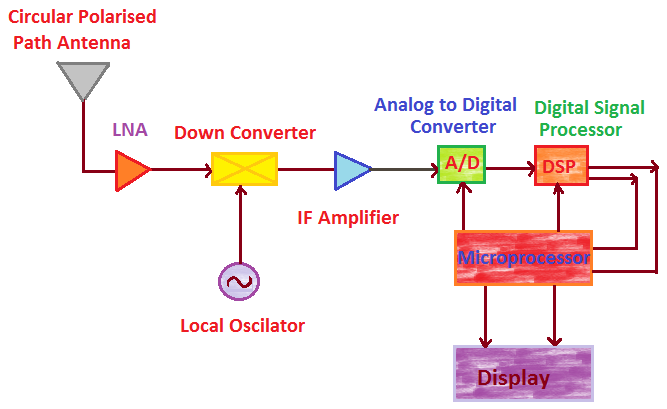
Figure is showing a simplified block diagram of a C/A code GPS receiver.
The Antenna is typically a circularly polarized path antenna with an LNA mounted on a printed circuit board.
A conventional receiver is used to generate an IP signal in a bandwidth about 2 MHz which is sampled using I and Q sampling techniques and processed digitally.
The digital portion of the receiver includes a C/A code generator, a correlator, and a microprocessor that makes the timing measurements and calculates the receiver position.
Most GPS receiver make use of a 12 channel IC chip set that can be purchased for about $25.00(year 2000 price).
At most, 12 GPS Satellites can be seen by a receiver at any one time, so the coding gain in the spread spectrum receiver must be sufficient to overcome the interference created by 11 unwanted signal while recovering the twelfth wanted signal.
The C/A and P code transmission from all GPS Satellites are overlaid in the L1 and L2 frequency bands, making GPS Direct Sequence Spread Spectrum (DSSS) System.

C/A Codes :

The C/A Codes transmitted by GPS are all 1023 bit gold codes.
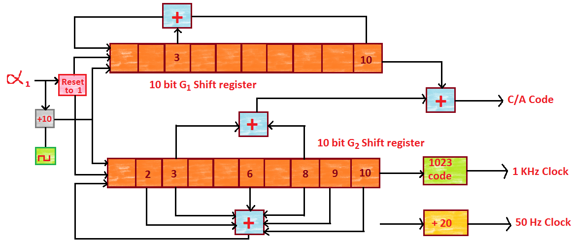
GPS C/A Gold Codes are form from two 1023 bit m-sequences, called G1 and G2 , by multiplying the G1 and G2 sequences with time offsets.
A m - sequence is a max length PN sequence which is easy to generate with a shift register and feedback tab.
A shift register with n stages can generate a PN sequence 2n – 1 bits in length.
The PN Sequence G1 and G2 are both generated by 10 bit shift register and therefore both are 1023 bits long.


